Introduction:
I've created a number of control systems over my career. Most of them have controlled moving vehicles, like airplanes or rockets. But some have controlled other systems.
The U.S. Navy's Sensor Driven Airborne Replanner
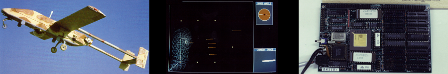
In 1989 I was part of a very small team that developed the world's
first fully autonomous UAV control system. The system was called the
Sensor Driven Airborne Replanner (SDAR). At that time, the Navy was
flying Pioneer UAVs (the airplane in the masthead at the top of the
page) off of the battleship USS Wisconsin, BB-64.
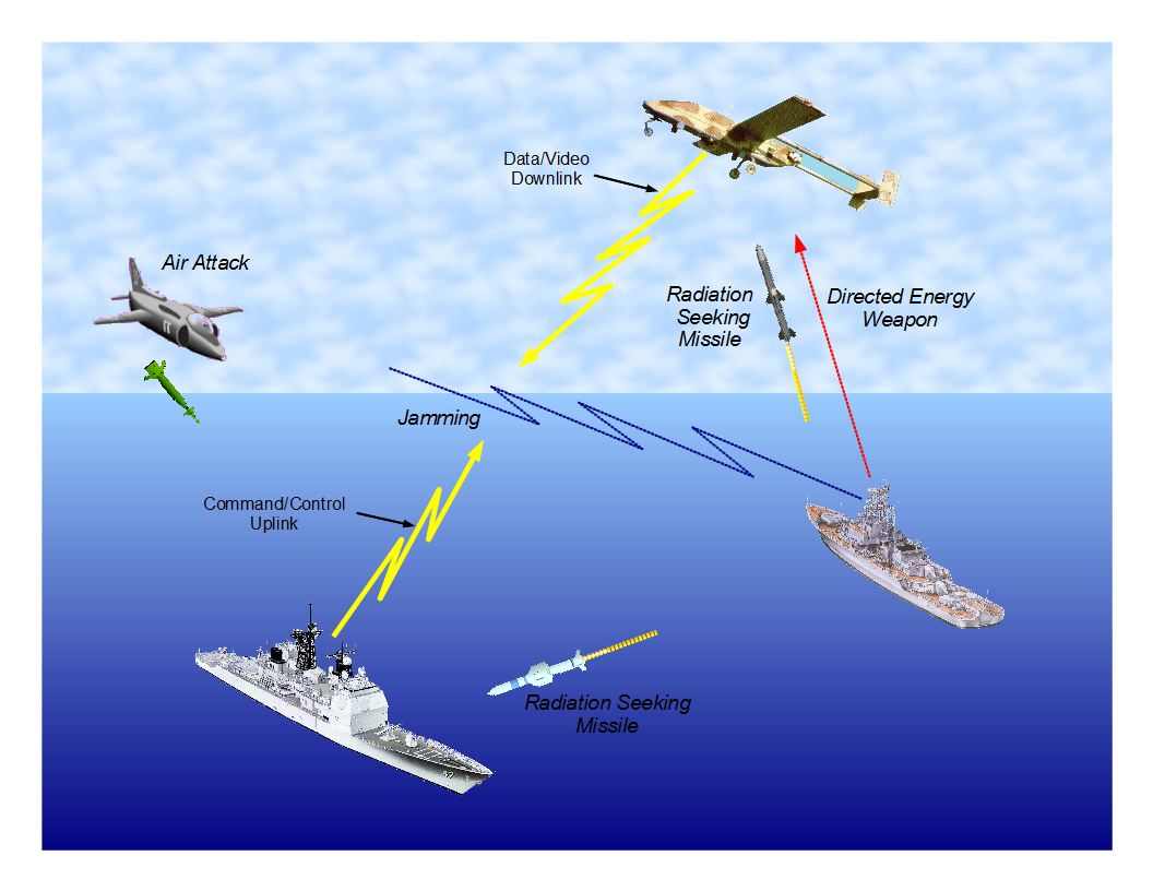 The UAVs were used for artillery spotting and over-the-horizon
search for enemy ships. At that time, the UAVs were controlled
through a continuous radio uplink to the aircraft. The aircraft
operated a continuous radio downlink to carry both data and video
back to the operators. Nearly all UAVs are still operated this way.
The problem with this technique is illustrated in the figure to the
right. (Click on any image on the page for a larger version.) The
radio links are susceptible to jamming, act as beacons
announcing the ship's presence,
and as localizers for any radiation-seeking weapon. We figured
out how to embody the intelligence of the ship-based mission-planner,
pilot and camera operator into the aircraft, eliminating the need
for both the control and data links, so that the UAV could operate
covertly. We did it by creating a control system
that could fly the aircraft as well as any pilot, topping that off
with a real-time artificial intelligence (AI) system that
could make high-level decisions, replanning the UAV's mission as data came in.
With this kind of intelligence on board, the UAV could fly a complete
mission autonomously and covertly, collecting the mission planner's
desired data without any input or contact from the surface.
The UAVs were used for artillery spotting and over-the-horizon
search for enemy ships. At that time, the UAVs were controlled
through a continuous radio uplink to the aircraft. The aircraft
operated a continuous radio downlink to carry both data and video
back to the operators. Nearly all UAVs are still operated this way.
The problem with this technique is illustrated in the figure to the
right. (Click on any image on the page for a larger version.) The
radio links are susceptible to jamming, act as beacons
announcing the ship's presence,
and as localizers for any radiation-seeking weapon. We figured
out how to embody the intelligence of the ship-based mission-planner,
pilot and camera operator into the aircraft, eliminating the need
for both the control and data links, so that the UAV could operate
covertly. We did it by creating a control system
that could fly the aircraft as well as any pilot, topping that off
with a real-time artificial intelligence (AI) system that
could make high-level decisions, replanning the UAV's mission as data came in.
With this kind of intelligence on board, the UAV could fly a complete
mission autonomously and covertly, collecting the mission planner's
desired data without any input or contact from the surface.
The SDAR system was essentially a heirarchy of feedback control systems. At the base, connecting the SDAR system to the aircraft, I created a bank angle-, altitude- and airspeed-command autopilot. This is what flew the aircraft. Above it, we wrote a set of heading-, course- and track-command navigational control algorithms. These allowed us to, for example, command the airplane to fly a track between two points. Finally, on top, we had the artificial intelligence system, which took in sensor data, made decisions on what to do next to perform the mission and then sent guidance commands to the navigation algorithms.
For more detailed information on the system, here are a few papers I've written on the system plus a video of SDAR in action.
 A paper I wrote for a computer programming conference that describes
the SDAR system and what it does.
A paper I wrote for a computer programming conference that describes
the SDAR system and what it does.
A white paper showing SDAR flying a simulated mission. This paper
goes into good detail on how SDAR works its way through a mission.
A paper on the hardware-in-the-loop simulation that I wrote for
the development of the SDAR system in the lab.
![]() A video of the SDAR system flying a simulated mission.
A video of the SDAR system flying a simulated mission.
Analytical Methods, Inc.
At AMI I designed a GN&C system for a collapsible-wing, man-portable UAV. The control system is NATO STANAG-4586 compatible, its Vehicle Specific Module making it controllable from any STANAG-compatible ground station. Most UAVs aren't really designed, as we think of it in the Engineering sense. Instead, they're built using intuition, trial and error in someone's garage and work as well as can be expected. At AMI, they have airplane design experts, and they applied their talents to this UAV, designing its airframe just as thoroughly and carefully as one would design any other aircraft. I'm not at liberty to say much about the system, other than it was a beautiful design and that it will serve its customers just as they desire. Here is part of the description of the system from the CTTSO's solicitation:
R2655 Enhanced Collapsible-Wing Micro Tactical Unmanned Aerial System
Develop a single-man portable and operable Enhanced Collapsible-Wing Micro Tactical Unmanned Aerial System (ECMTUAS) with a secure Mobile Ad Hoc Network (MANET) digital data-link and software-based C2 capable of hand-launch and internal transport in a man-portable canister. The ECMTAUS shall have an endurance of 60 (threshold), 180 (objective) minutes in the operational configuration that has the greatest power draw. The ECMTAUS shall have a minimum dash speed of 55 knots. The ECMTAUS airframe shall not exceed four (threshold), two (objective) pounds in weight; the transportation canister shall not exceed seven (threshold), five (objective) inches in diameter and 35 (threshold), 30 (objective) inches in length. The ECMTUAS shall be able to launch within 30 (threshold), 10 (objective) seconds of removal from its canister...
And here is a link to the solicitation for the system in the Defense Systems Journal
Masten Space Systems
At Masten Space Systems, I developed Guidance, Navigation and
Control (GN&C) systems for the
company's vertical takeoff/vertical landing rockets.
 Masten's vehicles are designed to take small payloads to high
altitude, where they can be outside most of the Earth's
atmosphere and where they can experience a short period of
near-zero-g flight. Upon reentry, the rocket can relight its engine,
right itself, make a controlled descent under rocket power and return
itself and the payload back the launch point, for a soft landing.
Masten's rockets have no aerodynamic control surfaces, and so all
control over the vehicle is exerted by vectoring the thrust of the
single, gimballed engine. I developed a new set of control laws
for Masten's "Xaero" vehicle. With those new laws in place,
the vehicle exhibited improved accuracy in its position and velocity
control during autonomous flight.
Masten's vehicles are designed to take small payloads to high
altitude, where they can be outside most of the Earth's
atmosphere and where they can experience a short period of
near-zero-g flight. Upon reentry, the rocket can relight its engine,
right itself, make a controlled descent under rocket power and return
itself and the payload back the launch point, for a soft landing.
Masten's rockets have no aerodynamic control surfaces, and so all
control over the vehicle is exerted by vectoring the thrust of the
single, gimballed engine. I developed a new set of control laws
for Masten's "Xaero" vehicle. With those new laws in place,
the vehicle exhibited improved accuracy in its position and velocity
control during autonomous flight.
MCI Site Controller
MCI's Site Controller is a mission-critical system that is located
in every phone network hub around the world.
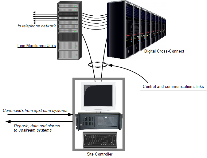 Its job is to control and communicate with the network equipment
that forms the backbone of the telecommunications network. The diagram
at the right shows how the system fits in. The central piece of equipment
in the phone system is the Digital Cross Connect (DXC). This
is the machine that connects disparate phone lines to form an
end-to-end, continuous connection. Every network hub, or
"site", has one or more DXCs located inside of it. In addition, line
monitoring units (LMUs), which sample the digital signals passing back
and forth, are placed on each digital phone line entering the site.
The Site Controller communicates with and controls the DXCs and LMUs
in real time. Upstream systems, whose jobs involve provisioning the
phone network, collecting performance information and collecting
alarms, do all of their work through the Site Controller. These
systems open a session with the Site Controller and then send commands
to schedule performance reports and manipulate the DXCs or LMUs.
The Site Controller complies by remembering what each session has
requested, sending commands to the network equipment, collecting
data at appropriate intervals, and sending that data to the upstream
systems.
Its job is to control and communicate with the network equipment
that forms the backbone of the telecommunications network. The diagram
at the right shows how the system fits in. The central piece of equipment
in the phone system is the Digital Cross Connect (DXC). This
is the machine that connects disparate phone lines to form an
end-to-end, continuous connection. Every network hub, or
"site", has one or more DXCs located inside of it. In addition, line
monitoring units (LMUs), which sample the digital signals passing back
and forth, are placed on each digital phone line entering the site.
The Site Controller communicates with and controls the DXCs and LMUs
in real time. Upstream systems, whose jobs involve provisioning the
phone network, collecting performance information and collecting
alarms, do all of their work through the Site Controller. These
systems open a session with the Site Controller and then send commands
to schedule performance reports and manipulate the DXCs or LMUs.
The Site Controller complies by remembering what each session has
requested, sending commands to the network equipment, collecting
data at appropriate intervals, and sending that data to the upstream
systems.
I created four Site Controller releases. For Release 11.0, I gave the system the ability to operate E1 (European standard) Line Monitoring Units. MCI was very good at recognizing critical systems and allocating resources to ensure their dependability. Each release of the Site Controller underwent three separate and increasingly stressful test regimens. First, our local, System Test group wrung it out in our local lab. If it passed their tests, it went to the Network Equipment Lab (NEL) in Richardson, TX, where it was stressed under a full load of site equipment carrying synthesized traffic. If it passed NEL's testing, it went to a single site in the field, under the watchful eye of the Field Verification Office (FVO), where it worked under real conditions with equipment carrying live traffic. If it passed FVO, it was released to the field. After the System Test people finished their examination of Release 11.0, I found myself greeted in the hallway with congratulations and handshakes. They were able to find 6 minor issues with the system. They were used to a typical count in the twenties. With those errors fixed, The release passed through both NEL and FVO without a single additional issue coming to light. For Release 12.0, I gave the system the ability to operate the Alcatel 1633 DXC. It passed through all testing without a single issue arising. For Release 13.0 I gave the system the ability to be reconfigured on the fly. And for Release 14.0, I gave the system the ability to operate the Alcatel 1631SX DXC. When I created that release, the 1631SX was still under final development, and so we didn't have one to work with. Its design was final, however, and so I wrote a program that turned a PC into a hardware emulator of the DXC. Using it, I was able to complete development of Release 14.0 very quickly, before the hardware was released. Releases 13.0 and 14.0 also passed through all testing without a single error being found. I was very pleased to receive a note of commendation from the System Test group for my work.